Overview
The Lateral Image (CCD or film) Test (LIT) combines the best of the Caustic & LWT and avoids their difficulties:
- The Caustic requires determining the Center of Curvature (COC) within 0.001". A difficult task (1 - page 223).
- With the LWT (3) each zone needs to be measured mechanically to better than 0.0005". A difficult task unless the room temperature is closely controlled i.e., distance from the mirror to tester changes with temperature while the readings are being taken.
LIT employees a Caustic type mask, each mask hole returning an images of the testers source,
which by the way is visible in an eyepiece. But unlike the Caustic, all the mask holes are
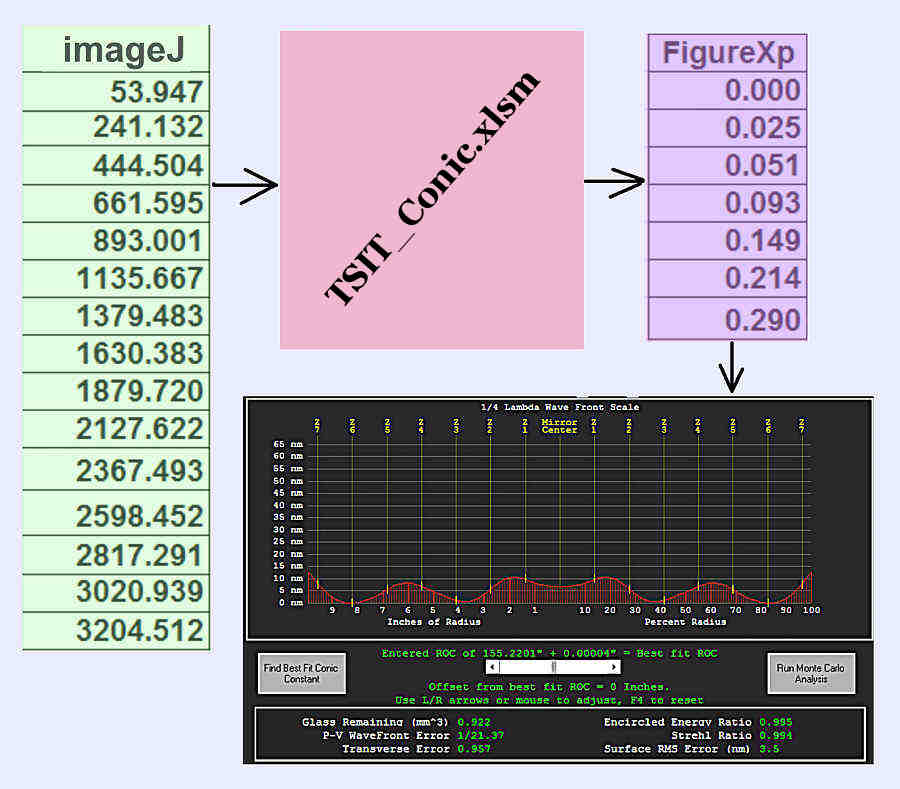
open allowing the capture of all the LWT measurements with one exposure. That image is then processed by imageJ without human judgement. Those results
are then the input to the LIT Spreadsheet, which computes Foucault's for a specified Conic Constant (not just a parabola).
The LIT spreadsheet equations were verified using sixtests.exe in the Caustic, Fixed Source mode.
That is, the LIT is a Caustic, Fixed Source test. The Caustic was invented by R. Platzeck and E. Gaviola as reported in Journal of Optical Society of America, 20 (November 1939).
Presentation of the LIT Test at the 2023 Portland Alt Az Workshop
Film Verses CCD
| |
For a digital SLR (lens removed), you need to know: |
| |
- Pixels per inch.
- Lens mounting to CCD spacing (4).
- Olympus E300 Evolt
- Lens mount to CCD: 38.8 mm
- Pixels/inch: 4771
- Canon T2i EOS Rebel
- Lens mount to CCD: 44 mm
- Pixels/inch: 5905
|
| |
In 2002, while figuring a 12.5” f/4.6, I was flunking Foucault 101, and that begain my use of film to figure that mirror. It worked and is documented here.
|
| |
For Film all you need to know is the DPI of the scanner |
| |
The slit image whether film or CCD is processed exactly the same.
|
|